Are you looking for how to learn embedded systems? Are you looking for a clear roadmap to start learning embedded systems? Are you a complete beginner and need no-fuss clear guidance on studying and experimenting with embedded systems
We’re going to cover all the above questions in this tutorial. And we’re going to see a clear roadmap to start learning embedded systems. We’re going to see what it takes for anyone to get started with embedded systems and what is the flow that one can follow if he or she wishes to excel in learning and developing embedded systems.
This tutorial is specially created for complete beginners to give the simplest guide to start learning embedded systems quickly and understand all that is there to learn about it. This tutorial will help you map your learning objectives based on where you are at this stage. Even if you’re in the middle of something like you understand a little bit of Arduino programming, this tutorial will help you shape your knowledge and is intended to provide guidelines to excel. So let’s get started.
What is an embedded system?

An embedded system is a dedicated computerized system that can perform one dedicated task or similar associated tasks. Let’s take an example of a temperature controller. This type of temperature controller is very commonly used in a wide variety of manufacturing industries. The typical jobs of temperature controller are
- Read the temperature value
- Display the temperature value
- Configure a set point for temperature value
- If the temperature is below the setpoint, make the output device off
- If the temperature is above the setpoint, make the output device on
- Repeat the cycle
As you can see in the above steps, its obvious that we do not expect an embedded system to stop functioning. An embedded system is always running unless its power off or turned off by the user. So to create such a simple system what are the options we have?
- Analog + Digital Design
- Embedded Design
Analog Design
Now such a system like a temperature controller, can it be built using a simple analog circuit? Yes, of course, it can be developed. By using temperature sensors, analog to digital converter, the seven-segment display drives and a lot of conditioning circuits and digital timer circuits. We definitely can create such a system for the temperature controller, but it requires a lot of design efforts. Moreover, if we want to change anything or any element of this system, it’ll be very difficult to make changes as we’ll need to reconfigure a lot of component values itself. Even if you want to add some time delay or some timed operations, you’ll need to make a lot of changes to the system. So what is the option here?
The option is instead of creating a simple circuit design, make it using embedded system principles.
Embedded Design

An embedded design if very simple to build. All it will consist of is the microcontroller unit which will do the job of sensor reading, display driving and output device (relay) switching. How it does all of this, how it prints the value and how it reads the temperature sensor and all is controlled by software written inside the controller. An embedded controller can not function directly as compared to normal analog or digital circuits. Instead, an embedded microcontroller needs a program written in its memory which will do the job of controlling the devices. The microcontroller is a reconfigurable IC. The pins of the microcontroller can do the job of input or output or analog input and so on. Depending on the software written, the pins of the microcontroller can behave differently. In order to get excelled in microcontroller coding, we need to understand the microcontroller architecture. After studying the microcontroller architecture well, we can start writing the programs for it. But because of this big limitation, many people can not dive into embedded systems directly. And here the Arduino board comes into the picture. In order to program an Arduino board, we do not need any knowledge of the underlying hardware which is called the microcontroller Board. We’ll discuss the Arduino board in detail soon.
How an embedded system is built?
So, a system that is built using this type of microcontroller as the heart of the system is called an embedded system. An embedded system has all the related input and output devices interfaced directly with the microcontroller or connected to it via some driver circuit. Depending upon the application at hand, an embedded system may have few or all of the components shown in the below diagram.
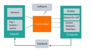
What are the different components of Embedded Systems?
Just take a look at the above block diagram. It’s a very simple block diagram of an embedded system. Mind well, when I say simple, it really is. The block diagram hides almost everything that is complex and gives a bird eye view of an embedded system. The embedded systems block diagram shows mainly 3 components of the embedded system.
Inputs can be usually coming from switches or sensors. In the example of temperature controller, the inputs will be switches to accept the setpoint and the temperature sensor itself. Just like, a plant watering system will have input as a moisture level sensor.
Controller is the heart of an embedded system. A controller’s job is to process the given inputs and generate outputs. For a temperature controller, the job of the controller inside is to read the temperature value, read the switches. Now compare the temperature value with a set point, and control output devices. Controller cannot do any of these things out of the Box and every controller needs software sitting inside it to do these things. This creates a demand for software programming in embedded systems.
The most popular controllers used in embedded systems are
- Microcontroller
- Microprocessor
- PLDs (FPGA / CPLD)
- System on Chip (SoC)
Outputs
This is the sole purpose of designing any system. We need to generate outputs. Usually, outputs are generated using a variety of driver circuits that can create output action. Microcontroller (if used) can only generate small signals as their output. +3.3v/0v or +5v/0v as output voltages. These voltages are very small and cannot drive any output device directly and hence we need something called as an output driver for turning things on or off. Outputs of embedded systems are in the form of below examples with their respective drivers
- LED On / Off (No Driver)
- Devices turning on / off. (transistor + relay driver)
- Motors rotating with varying speed (motor driver)
- Buzzer On-off and sound generation (no driver)
- Fan on / off (transistor / relay / thyristor driver)
- Sending SMS (GSM Module)
- Sending data over the internet to for remote monitoring (wifi interface)
- Displaying data on a screen (LCD / LED screen interfacing)
- And many more such things
Where Arduino fit in embedded Systems?
You’re reading this tutorial means one thing is sure, you’ve heard about Arduino 😊.
In an embedded system, generally, the most emphasis on study is given for understanding the controller. The developer of embedded systems has to be very good at understanding the microcontrollers used in the system with all of their instructions and way of writing programs for them. Every microcontroller is equipped with some or all of below-mentioned features which are used for properly programming an embedded systems
- Input / output ports
- Timers / counter
- Serial Ports
- Memory (RAM / Flash / EEPROM)
- Analog to Digital Converter
- Digital to Analog Converter
- Protocols interfacing (I2C / SPI)
- Interrupts ( To make processing faster and solve programming challenges easily)
- And many such user interfaces are on-chip
A single-chip microcontroller has all such features on the chip. In order to use any of these features, the microcontroller developer creates some unique way of configuring the microcontroller.
- First, there are unique instructions for every microcontroller, which can execute some jobs like reading / writing data from memory / Input-output ports / all the registers inside the controller.
- Secondly, there are many special function registers inside the microcontroller. And each feature may have one or many Special Function registers inside the microcontroller.
- The study of the Instruction set and all the internal register organization combinedly is called a study of Architecture of microcontrollers
So every embedded systems developer has to be very good at an understanding of the microcontroller architecture as well as the knowledge of inputs and outputs to be used. Every electronics/computer engineering student usually learns this as part of their studies and anyone else who is interested to excel in microcontroller studies has to study this on their own. One thing is sure that the proper understanding of microcontroller architecture is a must.
But
What about those hobbyists/artists who don’t know about microcontrollers and still want to make embedded systems?
For exact people like these, who don’t want to study architecture and get started developing systems faster and smoother, in 2005 Arduino boards were launched in Italy. There is a long history behind Arduino boards which can be read here. The sole purpose of Arduino is to enable non-techie people to get started with designing hobby projects using embedded systems.
But over the years, due to the open-source nature of the entire Arduino system, millions of people started using it including seasoned developers for very simple reasons
- Lots of clean libraries available for almost every single interface out there
- Free and open source
- Quick prototyping is possible
- It’s cheap
As of writing this tutorial, Arduino is undoubtedly the number 1 hardware prototyping platform. And there is no need to take any survey on that. Everyone will agree with this. This is how Arduino slowly got adjusted in the crowded market of microcontrollers.
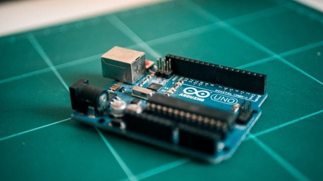
But what is Arduino anyway?
Arduino is a microcontroller-based board that is ready for usage. You don’t need to study the microcontroller architecture in order to use Arduino. You just should be able to read the board; understand basic English and you can get started with programming Arduino. I’ve written a separate tutorial about it which can be found here
Steps to Learn About Embedded Systems
Now that we’ve gotten a fair idea of how to create an embedded system, let’s jump to understand how to learn embedded systems. This will help you get a clear picture of how to get started with embedded systems and embedded programming.
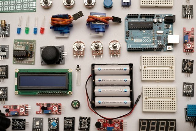
Understanding of basic electronics

The first thing then is to understand basic electronics. Probably one of the most important points. Everything we’re discussing here is electronics and hence having an understanding of electronic components, their workings, and their usages will prove to be very beneficial to learn embedded systems effectively. Electronic components are used in entire embedded systems development and hence you should know about them as much as you can. But to get started, understanding of below-mentioned things is the first step.
Resistors
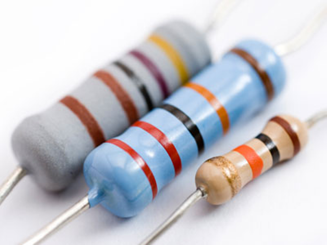
Resistors are those tiny little electronics components that oppose the flow of electric current. Whenever we try to build a small circuit, if a resistor is added into that circuit, the job of a resistor is to resist (or oppose) the current flow.
The value of resistance offered by a resistor never changes. Resistors are passive components means it doesn’t matter in which direction you connect it in a circuit, it will work the same way. By using resistors, we can limit the current flowing through a circuit. As seen in the previous tutorial, resistance offered by a resistor is measured in Ohms (capital omega symbol Ω)
Capacitors

A capacitor (originally known as a condenser) is a passive electronic component having 2 leads. A capacitor is used to store energy in an electric circuit. There are different types of capacitors that are used. But all they contain at least two electrical conductors plates which are separated by a dielectric i.e., insulator material. The conductors can be thin films of metal like aluminum foil. The ‘nonconducting’ dielectric material helps increase the capacitor’s charge storage. More about capacitor can be read at a very nice tutorial by adafruit here
Diodes

A diode is a unidirectional switch used in electronics. The job of a diode is to allow the flow of electricity in only one direction and blocking its flow in the other direction. Most primarily, diodes are used in a rectifier circuit. The rectifier circuit is used to convert AC voltage to DC voltage. Rectifiers are used to create power supplies. Apart from the rectifier, a diode is used in circuit protection and in a variety of applications where this conduction in one direction property is needed. More about it is here
Transistors
Transistors are used for mainly 3 types of circuits
- Switching
- Amplification
- Oscillation generation
In embedded systems, transistors are mostly used for switching purposes. In analog circuits like amplifiers and oscillators, transistors server different purposes. It’s a simple 3 terminal device that comes as either PNP or NPN transistor. Their properties differ in how they conduct electricity and how it can be controlled. Transistors theory can be read here
LEDs

LED’s are perhaps the most interesting electronic component that we use in the circuit. LED’s are (Light Emitting Diode) components which can emit a specific light. It can be RED, Green, Blue or Yellow. LEDs require very little voltage to turn ON (typically 3v) and they have a very long life. We see LED’s in power indicators in almost any electronic appliance. The power light we see on TV, DVD, microwave, in TV remote control are all LED’s. We have LED TV’s now a day’s which uses LED’s to give the backlighting to the LCD Panel in it. More about LEDs is here
Switching devices: relays
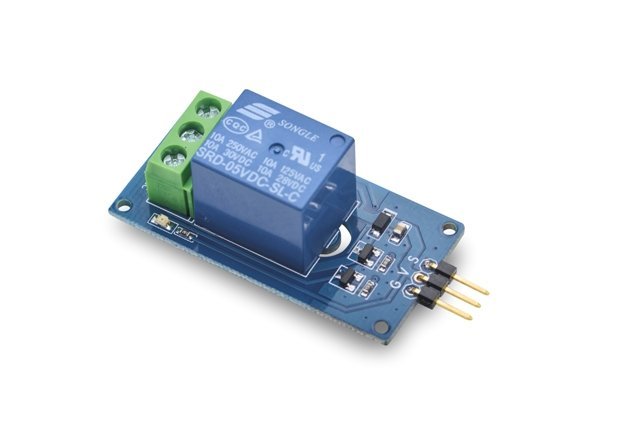
Switching devices and circuits are needed to turn on / off devices using microcontroller output. Usually, the output of a microcontroller board like Arduino or any other microcontroller is only a digital signal. This digital signal can have a value of either 1 or 0. Electrically, 1 means the operating voltage of microcontroller and 0 means the ground voltage. Usually, 1 stands for +5v or +3.3v and 0 stands for GND of DC supply or negative of the power supply circuit. This small voltage cannot turn on / off a physical device like a light bulb. So, this voltage is given to a transistor which turns on something called Relay. This relay then can switch the major AC appliances.
Understanding of basic C Programming

A microcontroller is programmed using instructions. This is called assembly language programming. In order to write effective programs faster, C programming is used. A separate software called cross compiler is used which can convert the C program to microcontroller understandable code. This microcontroller understandable code is then created in a special file format called a hex file. This hex file is then burned or written in the permanent memory of a microcontroller called flash memory. The microcontroller reads a program from flash memory and executes the program accordingly. This whole process is called embedded C programming. There are various Integrated Development Environments for writing embedded C programming. These IDE combine the cross compiler of microcontroller and text editor to give a smooth coding experience to the programmer. The choice of IDE depends on the microcontroller being used. For example, Arduino uses the Arduino IDE. Various other microcontroller uses different IDE tools. Some of them are free some are commercial versions. Here’s a shortlist of IDE’s used for various microcontrollers
AVR series microcontrollers by Atmel (Now Microchip)
- Atmel Studio
- AVR-GCC Programmer notepad
- codevisionAVR
- mikroC Pro for AVR
Microchip PIC
- MPLAB
- mikroC Pro for PIC
- CCS C Compiler
8051 and ARM architecture
- Keil Microvision
- Tasking
- IAR Embedded Workbench
Your first microcontroller: Arduino

Now you got the idea of what all to study in embedded systems. It’s best to choose with Arduino if you’re a beginner. Arduino provides easy access to microcontroller features with the help of ready-made libraries and software tools. Using Arduino will be the first step to enter into the embedded systems world. In order to study about Arduino, simply grab an Arduino board and start using it. You can download your first C program to Arduino very fast, mostly within 5 minutes. In order to use Arduino, you first need to install the Arduino IDE on your computer. Arduino IDE can be found at arduino.cc Depending upon your operating system you can download the appropriate and latest version of Arduino IDE. Once you have the board and IDE installed, you’re ready to get started with coding in Arduino.
Understanding controller IO
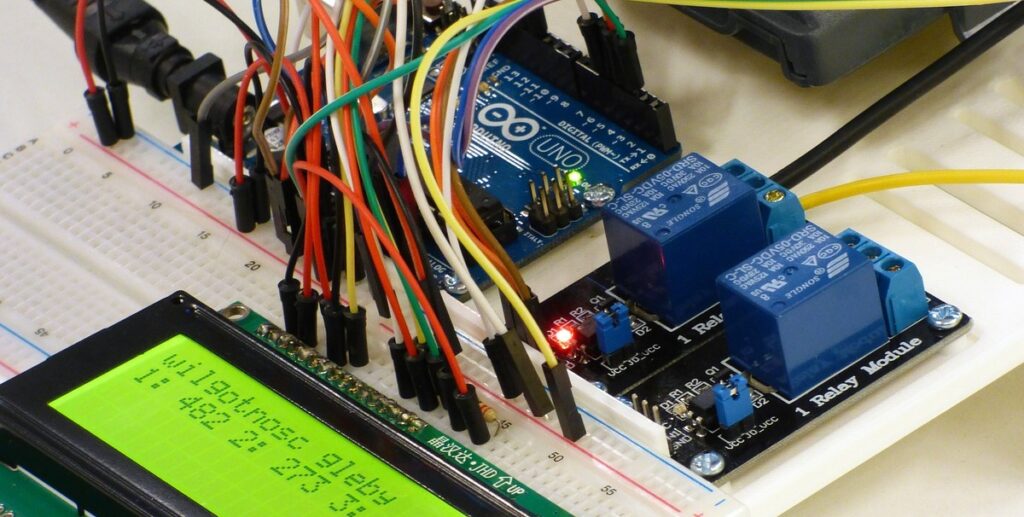
Once you download the first program on Arduino for blinking LEDs, the next step is to understand the nature of digital Input and output. Digital input and output of Arduino works with simple 2 functions. You can generate +5v or 0v output on any Arduino pin. You can also read the input pin on any Arduino pin, but for reading voltage on any Arduino pin, it must be either 0v or +5v. Arduino reads the input as LOW or HIGH. LOW means 0 volt and HIGH means +5v. We can read input using a
- Push-button
- Sound sensor
- Moisture sensor
- Infrared proximity sensor
- Many different modules
Reading inputs is made really simple with the digitalRead() function of Arduino.
Understanding IO interfaces, like a buzzer, Relay, digital sensors, LCD, etc
After understanding the basic digital input and output, the next step is to understand what all you can do with these functions. Now that you can read and write digital signal values, there are lots of possibilities open for you to create a number of different embedded systems. Even this much knowledge will get started with your hobby projects which can use a number of different interfaces like
- LEDs
- Switches
- Sensors
- Relays
- Buzzer
- Speakers
- LCD
You don’t need to understand everything with respect to Arduino or embedded systems to create a hobby project. For example, how to create a distance meter using the ultrasonic sensor? You need just enough knowledge of Digital IO of Arduino and you can connect an ultrasonic sensor to Arduino with LCD and measure distance and print it on the screen.
Interfaces using GPIO, stepper motor, DC Motor, etc
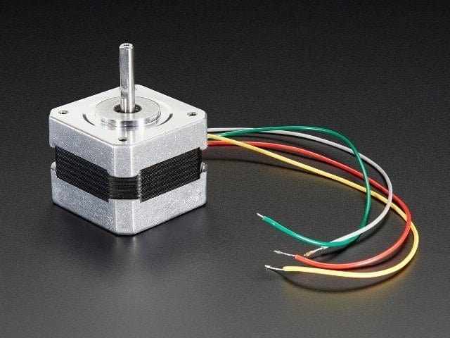
With simple input and output, you can control many different devices except simple relays. Relays are good to turn on/off any appliance but there are many other actuators who need controlling. These actuators include stepper motors, dc / ac motors, servo motors. The primary job of a motor is to provide a rotational force. A motor converts electricity into a rotational force for performing some action. It may include a robot movement, or a 3d printer or a robotic arm. And each type of motor requires a controlled supply given to it. DC motors need an H-bridge driver circuit. AC motors need thyristorised control circuit and servo motor needs a PWM pulse.
Most of the motor’s speed can be controlled by a time-varying digital signal given to them. This signal is called PWM. PWM is pulse width modulation. PWM signal means the digital output from an output pin which is not HIGH all the time; instead, it’s continuously made HIGH / LOW with varying duration of High pulse. This high-frequency pulse is responsible for the control action of motors. Most of the microcontrollers like atmega328 (the heart of Arduino board) do have on-chip PWM capability. A clear understanding of PWM helps us design better control circuits.
Serial Port or UART
Every microcontroller like atmega328 (the heart of Arduino Uno Board) has at least one serial port on it. Serial port, technically called UART is a module on the controller chip which allows the microcontroller to perform asynchronous serial communication. This asynchronous communication is made possible with 2 wires which are TXD and RXD. Apart from connecting these 2 wires, we also need to connect the GND wire from microcontroller to the device with which we’re communicating

TXD of microcontroller goes to RXD of the device with which we’re communicating
RXD of microcontroller goes to TXD of the device with which we’re communicating.
The speed of communication needs to be set before initializing communication. Since its asynchronous communication, there is no clock shared. Hence for synchronization, baud rates or bits per second of communication have to be pre-decided and set into the controller as well as the device with which we’re performing microcontrollers serial communication. Learning about Serial port of microcontroller opens up options to interface with many interesting peripherals like
- Bluetooth module (helps a mobile communicate with controller)
- RFID Reader
- GPS Receiver
- GSM Module (send/receive SMS and calls)
- Wifi interface
Understanding communication protocols, Serial, i2c, SPI

While studying about the devices which can be interfaced with a microcontroller, it’s very clear that only a few devices can be connected to the IO pins of any microcontroller. Because the number of input-output pins is limited, we cannot connect as many devices as we want to a microcontroller at the same time. Of course this limitation can be removed by using a higher microcontroller like atmega2560 which has more IO pin. But this can not be always done due to cost and size constraints.
In order to tackle such issues, some simple communication protocols are developed by industries to communicate a microcontroller with a number of different devices at the same time using the same common wire connection. And the most popular such communication protocol is called I2C which was developed by Philips (now NXP). Many other manufacturers call I2C as TWI. Because Philips invented I2C, only they use the name Inter IC Communication or I2C and others use a generic name like Two Wire Interface (TWI). I2C allows a microcontroller to communicate with up to 127 different devices using just 2 Wires. These 2 wires are SCL and SDA. Not to mention, the microcontroller can only communicate with one device on this bus at a time. Hence I2C is slower and usually used while interfacing with peripherals where speed is not a major concern like sensors.
Most common peripherals that support I2C protocol
- Real-Time Clock
- Accelerometer sensor
- Digital Compass Sensor
- Gyroscope sensor
- Analog to Digital Converters
- EEPROM Chips
Similar to I2C, there is another protocol called SPI, which was developed by Motorola. Since communication is happening on only 2 lines, I2C is slower. So when high-speed communications are needed, SPI or serial peripheral interface is required. SPI utilizes a full-duplex synchronous communication with Serial Data In, Serial Data Out, Clock, Reset and Chip select signals. SPI allows for much faster communication and usually used when high-speed data transfer is needed like memory card storage.
Popular SPI chips
- Memory Storage, SD Card
- EEPROM
- Function generators
- ADC and DAC’s
Interfaces based on communication protocols, ethernet, wifi.
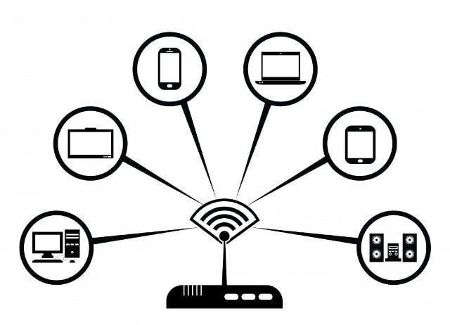
With the same I2C and (or) SPI Protocols some advanced network interfaces can also be interfaced with the microcontroller which allows the device to get connected to a LAN. A connection may be to a Lan or full internet connectivity is also possible. This internet connectivity then leads to a much larger application area we call as the Internet of Things. With a microcontroller, we can interface below-mentioned network interfaces to get connected to the internet
- Ethernet Interface Controller (SPI Protocol)
- Wifi Interface (SPI / Serial)
Understanding microcontroller (Atmega328)

With Arduino, we can use many features of microcontroller but still not all of them. In order to make the Arduino functional, some things are disabled by the Arduino firmware and hence you don’t have access to the entire feature set of the controller. And although as powerful it may be, most professionals and product development firms still consider Arduino only for amateurs. So, if you want to get a job in Industry, then you need to know the bits and pieces of embedded development from scratch; and it begins with an understanding microcontroller. With Arduino, we got the bigger picture of what things can be done using a microcontroller, the next obvious step is to understand how all that can be done using Raw microcontroller coding. And in order to do that, you need to first choose a controller. If you’ve used Arduino Uno before, then you have already used atmega328p which is the microcontroller on Arduino. So next best thing is to open the datasheet of this controller and start reading it.
How to read microcontroller datasheet

A device datasheet is the user manual of an IC provided by the manufacturer. Just like we get a user manual when we buy a new microwave oven. Consider if the microwave oven manufacturer doesn’t give a user manual with their product, what will happen? We won’t be able to use it properly. Hence probably, we won’t buy it. While the microwave is still a very simple device, an Integrated Circuit is a very, very complex one. Hence the manufacturer provides something called a datasheet for every device they produce. The purpose of datasheet is to enable the user to understand the IC and start using it easily. In a similar context, a microcontroller is also an IC, albeit a much more complex one. So, the microcontroller also gets a datasheet. We can download the device datasheet if we know who manufactured it from their respective websites. Otherwise, you can just web search with the name of the IC and you’ll find the datasheet.
Here’s a sneak peek of Atmega328 microcontroller datasheet’s first page

The datasheet provides with every single detail about the device we’re studying. But reading datasheets directly is not very simple for a beginner. It’s very confusing because every manufacturer organizes and shows data differently. But usually, there are some common grounds whenever you view the device datasheet of any IC. Be it microcontroller or a simple Op-Amp, there are some common things that are there in the datasheet and understanding them will make things simpler. They are as follows
- Features
This section contains a birds-eye view of the entire controller. It lists all the features of that microcontroller in a single list view. Just by reading this page, you can understand most of the features of a microcontroller.
- Pinout Diagrams
This section usually contains the pinout diagrams of the various packages of a microcontroller. The pinout in PDIP package as well as all the other SMT versions of packages. This section gives the user the pin number and names. If you want to create a package of this device in your favorite PCB design software, then you’ll need this section. Also, it’ll help a programmer understand which pins are GPIO and which pins are for timers and serial ports and I2C and so on
- Pin functions
In this section, the job of each pin is described in detail. We’ll understand which are power pins, which are oscillator pins and which are gpio pins. Most microcontrollers have more than one function associated with every single pin, and all of them will be described in detail over here.
- Internal Block Diagram
This section gives an internal block diagram of the microcontroller. In theoretical studies, its called the “Architecture of Microcontroller”. The name justifies because this block diagram shows everything that is there inside the microcontroller IC. But now every circuit is laid out in detail. Instead, it gives a complete overview of all that is inside the controller. It helps to know things better about the controller.
- Electric Specifications
This section details the different electrical specifications of a microcontroller IC. All the electrical specifications including
- Maximum and maximum operating voltages, IO voltages
- Operating temperature ranges
- Minimum and Maximum Current and power consumption ratings
- DC Characteristics
Features Explanation in detail
This is perhaps the biggest section of them all. This section shows all the workings, the internal registers descriptions, how to configure each one to be used. And how to use every single feature of the microcontroller. This section has it all. Whatever that you’re trying to use, be it an interrupt or timer, or ADC / DAC, you can use it by following this section here.
Concluding Remarks
Now that you’ve got a fair idea of what are the embedded systems, it’ll be a good idea to get started with your own experimentation. There are plenty many tutorials available on the particular microcontroller which you want to start learning embedded systems. If you want to learn embedded systems on Arduino, we have a detailed course on it here. Thanks for reading
[button link=”https://learn.kitflix.com/how-to-start-learning-embedded-systems-a-complete-roadmap” type=”big” newwindow=”yes”] Download this tutorial as ebook Here[/button]